As I am writing this, me and my team are almost done developing and polishing our game Size Matters from the GGJ 2012 for commercial release. The only things left to do are some art and gui work, and organizing and perfecting our collection of levels.
I’ve solved quite a few problems during the making of this game, and today I will be writing about one of them. First some background story.
Introduction
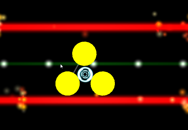
The first prototype of the game was made during the Global Game Jam 2012 in Hilversum. We had a small team and thus we decided to rely heavily on Unity’s strengths namely built-in physics and ease-of-use. (In an ad-hoc team not everyone will be familiar with any chosen game engine) So we quickly made a fun game just by scaling and duplicating the standard cube, and using that in our levels. Anyone who’s seen the original trailer or played the game will realize it looks pretty blocky. This was the result of building everything out of cubes and together with our chosen art style, we did not need any artists.
After the jam was over and realizing we were going to develop this thing for real, I took the time to create a proper editor for level building to allow for smoother lines and an easier workflow than messing about with tons of cubes. Essentially, we wanted some kind of vector drawing editor in Unity. Goals of this system:
- Allow for both straight line segments and curves
- Easy to create and edit lines
- Separation between visual and collision meshes
How it’s done
Data
The first step is determining what data you need and how you want to organize it. For our purposes, it was logical to create a Line class inheriting from MonoBehaviour to stick on a gameObject. This meant we could make prefabs of lines or edit them directly in a scene.
This Line component then contains a list of serializable control points, which determine where it goes and how it curves. A ControlPoint has the following properties:
- Vector3 Position
- Vector3 Tangent1
- Vector3 Tangent2
- bool Curved
A ControlPoint also has the Handle1 and Handle2 properties, which are useful shortcuts to allow editing of the tangents in an intuitive way. While a tangent represents a direction and magnitude, a handle represents the position of the control point added to the tangent.
The boolean property Curved is not strictly necessary as it is also possible to set both tangents to zero and achieve a similar result, but it helps to simplify certain calculations in a later stage when the meshes are created.
There are many other ways to do curves, such as Catmull-rom and NURBS. We chose to use Bezier curves here because of the balance between complexity and flexibility. It’s also familiar to anyone who has used vector drawing programs such as Inkscape or Illustrator.
We’ll also store some extra settings in the Line to define visual line width, collider width, and curve resolution.
Editor
The second step is creating an editor to make this data accessible without having to dive into an obscure list to change numerical values at random. Here we see another strength of Unity in it’s extendability. We can simply replace the default Line inspector with our own by creating a new class, inheriting from Editor and adding the CustomInspector attribute.
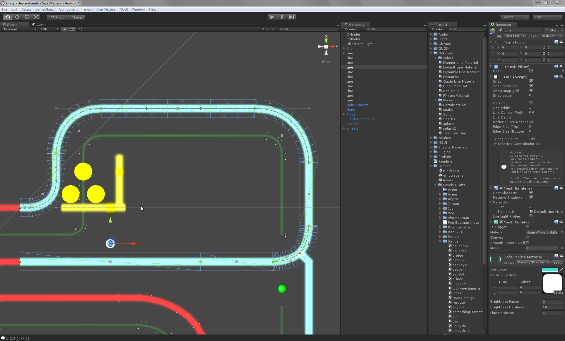
We can implement OnInspectorGUI to change the contents of the inspector itself, and we can implement OnSceneGUI to draw all our lines and edit handles in the scene view using the Handles class.
Every editor event, the OnSceneGUI method will iterate over all control points in the line and draw lines connecting them. For every control point, it will also draw handles for position and tangents so the level designer can simply drag them around the scene.
This is probably also the time where you start wondering about how to draw curves. Conveniently there is already a Handles.DrawBezier method available for us courtesy of Unity. But in the next stage, we will have to familiarize ourselves with the bezier function.
Of course sometimes special operations are needed so having functionality to select control points is also a good idea. This, for example, allows the user select a point and delete it, or select an endpoint and create new points from there onwards. These special operations can be triggered from the inspector, or in response to a shortcut, or both.
Another feature that turned out to be very useful is snapping. Unity editor handles give you raw data, so if you want any sort of snapping, you’ll have to do it yourself in the editor script.
Processing
Now that we have our data representation of lines and the ability to edit them, it is time to make them actually useful by generating meshes from them. Again we’ll divide this process up into several steps.
The first step is to take our collection of control points which define our line and convert it into something sensible to work with. We iterate over all control points and use them to create a list of straight line segments. For the normal control points this is simply copying their position. For the curved control points, we need to create some intermediate points to follow the curve’s shape at a predefined resolution. We iterate over these points while increasing a progress variable t from 0 to 1. We feed this to our cubic bezier function to get the required position at each point on the curve.
public static Vector3 Bezier3(Vector3 s, Vector3 st, Vector3 et, Vector3 e, float t) {

return (((-s + 3 * (st - et) + e) * t + (3 * (s + et) - 6 * st)) * t + 3 * (st - s)) * t + s;

}
Once we have this segmented line, the next step is to convert it into a Mesh. We can iterate over all the points and construct the mesh in parallel. Every line segment will correspond to two triangles, the size of which is dependent on the width of the line. Another approach is to simply create an outline and feed that to a polygon triangulation library.
Do this two times and you will have a render mesh and a collision mesh, both with different sizes. It is advisable to modify the collision mesh into something with depth, as Unity physics does not really like flat meshes.
And that’s how you make a 2D vector line editor in a 3d engine like Unity. Hopefully, some of you will find this post useful, or maybe you got some new ideas of your own.